Electrical Help

The technical area for everything relating to your powerplant. Post your questions and answers here...

Moderators: Alacrity, Rapier

User avatar
Mirak
Posts: 139
Joined: Fri Feb 06, 2009 4:10 pm
CMBA Member: 672
Location: Hampshire, UK
Contact:

Re: Electrical Help

Post by Mirak »

That looks more like an IN4000 series diode to me and is most likely the cause of the drop in voltage to 11.2 volts.

Depending on what's coming out of the Alternator at that point, it will be providing half wave rectification of the current and/or blocking reverse current.
If there's a regulator in the alternator, then you'll be getting 13 to 14 DC volts on charge with the engine running and the diode isn't needed. (13.6-ish volts with a charged battery.)
If there's no regulator, then it'll be AC coming from the alternator and you should have a lot more than a single diode.
If the alternator is running free without regulation, it could be generating 250v AC! So wear your waders if wet ;-)
As you've been measuring 12 and 11.2 volts DC, there's most likely a regulator in there and I can't see why the diode should be required.

If your instruments are 6v, then you'll need to provide a voltage dropper/regulator to them. "They don't like 12 volts up them Mr. Mainwairing."
They'll read inaccurately at best and probably blow the backlight bulbs if fitted.

All in all - typical boat wiring in my experience. Have fun.

cheers,
S
********************************************************************************
* Swinging the World by the tail since 1960 *
********************************************************************************

Quigs
Posts: 83
Joined: Thu Oct 25, 2012 9:32 pm
CMBA Member: 0

Re: Electrical Help

Post by Quigs »

Many thanks, I had to read that a few times before it eventually sunk in :notworthy:

So just to be sure, as the thought of 250v AC does scare me a little, should I fire up the engine without the diode connected and measure what Im getting out the back of the alternator? If its 13.6ish then I can get rid of the diode and replace with a normal wire?

With regards the 6v regulators, Ive just ordered another 2 for my oil pressure and fuel gauge. I believe one isn't needed for the volt meter?

Thanks again :D

User avatar
Mirak
Posts: 139
Joined: Fri Feb 06, 2009 4:10 pm
CMBA Member: 672
Location: Hampshire, UK
Contact:

Re: Electrical Help

Post by Mirak »

Fire the engine up - Don't panic about the mains level AC coming from the alternator - you're already seeing about 12 volts.

You should have two connections to the Alternator if it has an internal regulator - one heavy charge feed to the battery and a lighter one which is the field sensing line - that tells the regulator what the battery voltage is and controls the charge output. The alternator will also earth back to the negative side of the battery via its mounting on the engine.


With everything connected, your volt meter should read higher than 12 volts when the alternator is charging correctly. If it reads below 12volts then its likely that the regulator or alternator is broken and its worth getting it checked out.

And you won't need a 6 volt regulator for the voltmeter. Although if you have backlight bulbs in the instruments, check the voltage of those.

S
********************************************************************************
* Swinging the World by the tail since 1960 *
********************************************************************************

Quigs
Posts: 83
Joined: Thu Oct 25, 2012 9:32 pm
CMBA Member: 0

Re: Electrical Help

Post by Quigs »

Excellent, all makes sense but again, just to clarify :oops: .

Yes I do have the two connections, like you say the heavier red charge wire and the lighter one which is the one in the photograph with the in-line diode. This one goes to the + side of the coil. At present I have disconnected this one in order to get the 12.6v to the coil. Should I leave this disconnected during and after firing up and measure the voltage from the alternator?

If everything appears runs and reads ok, does this mean I can remove the diode to ensure I get the 12.6v to the coil at all times?

Thanks and sorry for all the questions! Don't fancy me paying you to come down and sort it out? :hmmm:

User avatar
Mirak
Posts: 139
Joined: Fri Feb 06, 2009 4:10 pm
CMBA Member: 672
Location: Hampshire, UK
Contact:

Re: Electrical Help

Post by Mirak »

Blimey - sound like this one was wired by an Iraqie pick-pocket!

The coil's positive side should be fed from the ignition switch - giving a full 12v - no ballast resistor.

Normally you would have an ignition warning lamp where your diode is (so THAT is what it's doing!) Creating a similar drop in voltage to force the alternator to charge, but of course, no warning mechanism for when the alternator stops charging... (light comes on when there's no charge). The benefit of the diode, I guess, is that you're not wiring to the dashboard and back - but there's no reason why you couldn't have a bulb holder taped to the loom.

Take a look at the diagram below - I basically stole it from an MG-B Haynes manual and added the extra bits I needed for my boat. Negative Earth; Alternator with internal regulator; 12 volt coil - the only weirdo is the the 12v feed to the carburettor which switches the fuel off when the ignition switch is turned off.

Your layout will vary...
Simmonds Ski Boat Wiring diagram - S. Pett 2008
********************************************************************************
* Swinging the World by the tail since 1960 *
********************************************************************************

Quigs
Posts: 83
Joined: Thu Oct 25, 2012 9:32 pm
CMBA Member: 0

Re: Electrical Help

Post by Quigs »

Its slowly making more sense.... :thumbsup:

The coil is still fed direct from the ignition for which Im now getting the full 12.6v but only after I take the diode off. If I reconnect the diode back onto the alternator, the voltage at the coil and through all of the ignition live feeds all become 11.2v.

Im still confused as to what I do with the diode wire. Should I take this wire back to an ignition live with a bulb holder in it and not back to the coil? :grrr:

Sorry for sounding thick! :oops:

User avatar
Mirak
Posts: 139
Joined: Fri Feb 06, 2009 4:10 pm
CMBA Member: 672
Location: Hampshire, UK
Contact:

Re: Electrical Help

Post by Mirak »

Your ignition switch and positive coil connection should be connected anyway. They are connected back to the alternator's regulator feed via the diode. Check your wiring bit-by-bit against the diagram.

I would just change the diode for a small 12v panel bulb and holder.

Bulb should light up when the ignition is turned on - and go out once the alternator starts to charge when the engine is running. You should then be seeing something like 13.5 volts at the coil/battery if the alternator is charging. As the battery charges the voltage will creep up - anything up to 14 volts depending on the regulator settings.

If you don't then its likely that the alternator is not charging properly and the voltage drop to 11.2 volts is caused by the current load of the coil and the alternator field.

After you turn the engine off, the voltage will drop slowly to about 12.1v (depending on the charge state of the battery).

If all of the above doesn't happen right - then the alternator is probably knackered or the wiring is even worse than we thought ;-)


Cheers,
S
********************************************************************************
* Swinging the World by the tail since 1960 *
********************************************************************************

Quigs
Posts: 83
Joined: Thu Oct 25, 2012 9:32 pm
CMBA Member: 0

Re: Electrical Help

Post by Quigs »

Probably the latter.... :nice: ....not!

It would be no hardship to run a light upto the dash anyway, so once Ive had a trial go with the bulb, I'll connect it up properly if all seems to work ok. Can't thank you enough for your input and that diagram will prove invaluable. :notworthy:

Quigs
Posts: 83
Joined: Thu Oct 25, 2012 9:32 pm
CMBA Member: 0

Re: Electrical Help

Post by Quigs »

Im losing the will to live here, as many of you reading this are probably to.. :grrr:

So Ive been out tinkering again trying to rig up the lamp however I can't get the lamp to light up. I connected the wire off the small terminal off the back of the alternator and with ignition on, no light.

I tried messing about the diode again and instead of taking the feed off the coil for it, I took it direct from an ignition live but still got the 11.6v throughout the system.

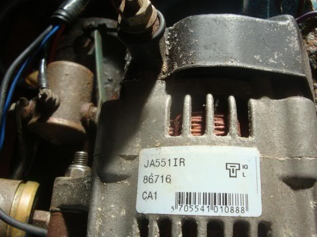
So Ive had another thought. If you look at the photograph you will see the back of the alternator has two terminals relevant to the diagram on top i.e. IG and L. Do you think I need to provide a live feeds to both of the terminals with the lamp coming off the IG terminal? I thought I'd ask before I did it!

Image

User avatar
Mirak
Posts: 139
Joined: Fri Feb 06, 2009 4:10 pm
CMBA Member: 672
Location: Hampshire, UK
Contact:

Re: Electrical Help

Post by Mirak »

Try this:-
ND alternator diagrams.pdf
(402.84 KiB) Downloaded 793 times
Japanese Alternator, used on Daihatu's

Send me PM with your email address for the whole pdf document.


S
********************************************************************************
* Swinging the World by the tail since 1960 *
********************************************************************************

Post Reply